Evaluation of the Accuracy of Free-hand C1 and C2 Screw Placement
Article information
Abstract
Objective
Posterior atlantoaxial fixation is an effective treatment for various pathologies. The anatomies of the atlas and axis are highly complex, and thus, freehand placement of C1, 2 instrumentation is technically challenging. The objective of this study was to evaluate the accuracy and safety of C1, 2 screw placement without fluoroscopic or any other guidance method by a 2-year spine surgeon.
Methods
A retrospective analysis of radiologic data was performed on all patients that underwent C1 or C2 instrumentation from April 2019 to January 2020; all procedures were performed by a 2-year spine surgeon. Computed tomography was used to assess cortical breaches of screw placement at C1 or C2. Severities of breaches were quantified using percentages screw diameter beyond cortical edges (0=cortical touch, 1≤25%; II=26-50%; III=51-75%; IV=76-100%).
Results
The surgeon placed 16 C1 screws and 20 C2 screws in 10 consecutively treated patients. For C1 screws, there were 4 breaches (25%), of which 3 were medial (18%) and 1 was anterior (7%), and for C2 screws, there were 3 total breaches (15%), of which 2 were anterior (10%) and 1 was medial (5%). Breaches were classified as grade I in 3 cases (42.8%), grade III in 1 case (14.4%), and grade IV in 3 cases (42.8%). No clinical sequelae were attributed to these breaches.
Conclusion
Although 25% of C1 screws and 15% of C2 screws placed using a freehand technique without guidance may be achieved accurately and safely. Preoperative morphometric evaluation and controlled exposure to this unique anatomy are essential to improve screw placement.
INTRODUCTION
The atlantoaxial junction, including the atlas (C1) and axis (C2), is a highly specialized area of the spine. They are quite different from other vertebrae and are anatomically complex. Atlantoaxial instability is extremely dangerous and can be caused by trauma, congenital malformation, a tumor, or inflammation. Posterior atlantoaxial fixation provides an effective treatment for atlantoaxial instability [1].
Posterior transarticular screw fixation for atlantoaxial instability is an accepted method of achieving rigid internal fixation [2]. However, the technique is technically demanding and requires considerable experience. In 2001, Harms and Melcher first introduced the screw-rod system for C1-C2 fixation. This instrument provides excellent immobilization with fewer complications than other posterior atlantoaxial fixation instruments [3,4] and is currently the most widely used technique. Many modifications of the original screw-rod system have been reported. Nevertheless, there remains a risk of damaging surrounding neurovascular structures, such as the hypoglossal nerve, vertebral artery (VA), C2 nerve root, and internal carotid artery (ICA) [5-7]. To avoid these neurovascular complications, various entry points, such as the posterior arch (PA) and superior lateral mass (SLM) have been used for C1 screw fixation [8]. The PA entry point enables the placement of longer screws and improves pull out strength to the level of that achieved by bicortical lateral mass screws [9]. The SLM entry point may be useful for avoiding VA injury (VAI) when there is a persistent intersegmental artery below the C1 arch [10,11].
The C2 pedicle screw is considered the primary option for C2 instrumentation because of its biomechanical stability. However, C2 pedicle screw placement is technically demanding for some C2 morphometries, especially when associated with neurovascular structures such as a high riding vertebral artery (HRVA). Furthermore, the presence of HRVA, which is not uncommon, can make instrumentation difficult and increases the risk of severe, even life-threatening neurovascular complications [10]. In fact, some authors have reported C2 pedicle screws are unsuitable in up to 22% to 31% of patients [12]. To address this problem, fixation techniques have been developed for alternative C2 screws [13], such as translaminar, superior and inferior pars screws, which are frequently used to avoid neurovascular injury in patients with HRVA [14].
Intraoperative fluoroscopy and other guidance methods have been used to ensure safe placement of screws. However, these methods are time-consuming and often expose patients to additional radiation. In this study, we investigated the breach rates associated with anatomical free-hand placement of C1 and C2 screws as performed by a 2-year spine surgeon at a single hospital without any expert guidance.
MATERIALS AND METHODS
1. Patients
The medical records and radiologic data of patients that had undergone posterior C1 or C2 instrumentation using the free-hand technique from April 2019 to January 2020 were retrospectively analyzed. The inclusion criteria were as follows: (1) receipt of C1 or C2 screw fixation and (2) availabilities of pre- and postoperative plain radiography, thin-slice computed tomography (CT), and angiographic CT findings, and (3) complete medical records. Patient age, sex, diagnosis, length of fusion, and details of complications were obtained.
Morphometric measurements of C1 and C2 were obtained from preoperative CT scans of bilateral pedicles. Coronal, axial, and sagittal CT reconstructions were reviewed to determine distances between screw entry points to midpoints of C1 posterior tubercles, lengths of screw projections, screw convergent angles, heights of C1 posterior laminae at screw entry points, widths of C1 pedicles, widths of the midportions of C1 lateral masses (Fig. 1), axial pedicle diameters, axial pedicle angles, maximum axial canal diameters, and lengths and diameters of axis laminae of C2 (Fig. 2).
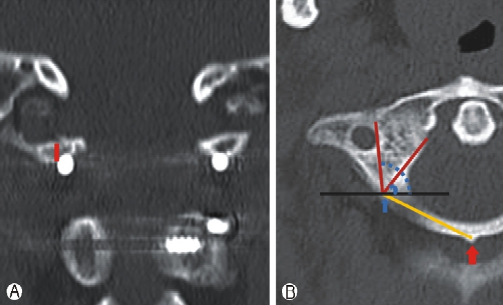
Morphometric measurements of C1 on an axial CT image. (A) Height of C1 posterior lamina at the screw entry point (red line). (B) Mid-point of the C1 posterior tubercle (red arrow), screw entry point (blue arrow), and the distance from the screw entry point to the mid-point of the C1 posterior tubercle (yellow line). Screw safety angle; medial to the spinal canal (blue line) and lateral to the transverse foramen (blue dot).

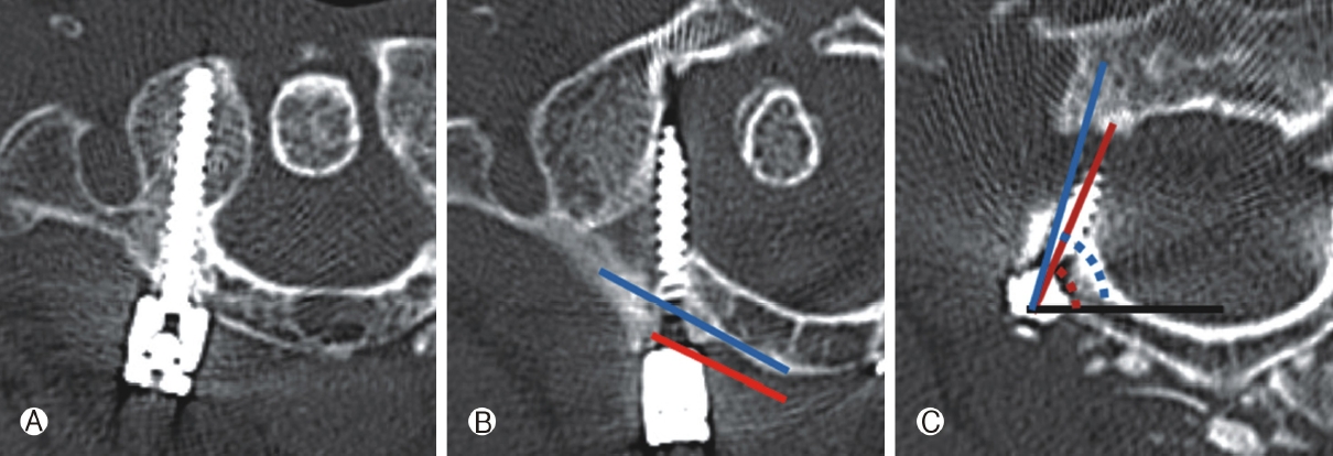
C2 morphometric measurements on an axial CT image. (A) Axial pedicle diameter (red line), maximum axial canal diameter (blue line), and axial pedicle angle (yellow line). (B) Length of the lamina (red line) and diameter of the lamina (blue line).
The presence of HRVA was defined as an isthmus height of ≤5 mm and/or an internal height of ≤2 mm on sagittal images 2 to 3 mm lateral to the cortical border of the spinal canal at C2, and/or a pedicle width of ≤4mm on axial images [15] (Fig. 3).
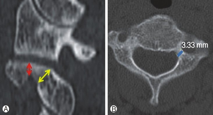
The three radiologic measurements were used to define the presence of a high riding vertebral artery (HRVA) on cervical CT images. (A) Parasagittal CT image showing heights of the superior pars(red arrow) and isthmus(yellow arrow). (B) Axial CT image showing a narrow left C2 pedicle (blue line). HRVA was defined as a superior pars height of ≤2 mm, an isthmus height of ≤5 mm, and/or a pedicle width of ≤4 mm.
Breach rates were determined from axial and coronal reconstructions on postoperative CT scans. The severities of breaches were graded using percentage screw diameter beyond cortical bone (0=cortical touch; I≤25%; II=26-50%; III=51-75%; IV=76-100%).
2. Surgical techniques
1) C1 posterior arch placement
In each case, the C1 posterior arch (PA) was subperiosteally dissected along the posterior arch using a nerve freer or a No. 4 Penfield dissector in a mediolateral direction. The screw entry point was defined as being in line with the 2-3mm lateral of the center of C1 lateral mass and was located on the middle of the posterior arch. When the thickness of the posterior arch was <4 mm, a “notching technique” was used (Fig. 5). The vertebral artery running above the posterior arch was protected with a Penfield dissector No. 2 while the entry point was decorticated using a 2.0 mm burr. The first 10 mm was inserted with a 2.0-mm burr, converged 10°, and was aimed toward the anterior tubercle of the atlas in the sagittal plane to avoid damaging the occipito-atlanto joint. This hole was then tested for cortical breaches and when negative, drilled with a 3.0mm drill bit using a drill guide. The screw hole was then measured and tapped, and a 3.5 mm polyaxial fully threaded screw of appropriate length was inserted.
C1 PA notching technique. (A) The height of the C1 posterior arch was smaller than 4 mm. (B) Ponticulus posticus. (C) Trajectory and ideal placement of C1 PA notching on sagittal and coronal postoperative cervical CT images.
2) C2 pedicle screw placement
While preserving semispinalis cervisis, C2 spinolamina and pars were subperiosteally dissected using a nerve freer and a No. 4 Penfield dissector. The screw entry point was located at the craniolateral quadrant and the lateral aspect of the C2 lateral mass. The trajectory of the C2 pedicle screw was determined under direct intraoperative visualization using superior and medial pedicle slopes. When the starting point and trajectory had been determined, a pilot hole was made with a small burr at the starting point. A gearshift and tapper were used to determine C2 pedicle screw paths. We relied on tactile feedback using a ball-tip probe to identify cortical breaches, and screw length was determined using ball-tip probe depth. The C2 pedicle screw was then placed.
3) C2 alternative screw placement
Alternative screws, that is, translaminar and pars screw, were used for C2 instrumentation in patients with HRVA. A translaminar screw was placed into lamina as described by Wright [16]. The inserting point was at the junction between the lamina and spinous process, and the screw path was directed contralaterally with a trajectory slightly less than the downward slope of the lamina. A gearshift and tapper were used to determine intralaminar screw paths. We relied on tactile feedback using a ball-tip probe to identify cortical breaches. Screws were placed when there was no abnormal finding. If in doubt, we made a small hole in the opposite lamina to determine whether the screw was inserted precise into the lamina (Fig. 7B). The probe, tapper, and screw were visualized through the hole and to ensure adequate C2 translaminar screw placement [17]. The entry point of the pars screw was 2 to 3mm lateral and 2 to 3 mm above the medial aspect of the C2-3 facet (similar to a C1-2 transarticular screw) and its endpoint was just behind the C2 transverse foramen. The screw trajectory was 10° to 20° medial along the C2 pedicle and vertical along the C1-2 facet joint. The gear shift, tapper, and ball-tip probe were used in the same manner as described above. In all cases, the entry point and screw length were chosen using preoperative CT images. Tactile feedback using a ball-tip probe was an important aspect of the safety and accuracy of C2 pars screw placement [17](Fig. 6).
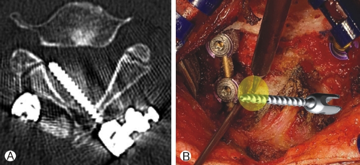
C2 translaminar screw insertion. (A) Type IV medial breach with a lamina distance of <4 mm. (B) A small bure hole was placed on the opposite lamina to ensure accurate screw insertion (yellow circle).
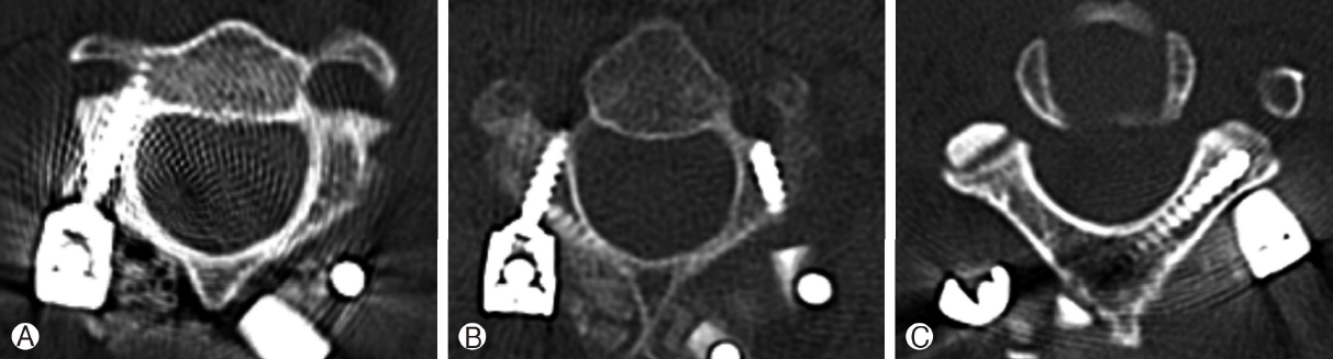
Trajectories and ideal placement of the three C2 screw types on a postoperative cervical CT image. (A) Pedicle screw. (B) Pars screw, and (C) translaminar screw.
RESULTS
Ten patients (7 men and 3 women) were included in the study (Table 1). Median patient age was 61.0 (49-91) years. The reasons for surgery were degenerative disease in 6 patients and traumatic instability in 4 patients. A total of 16 C1 screws were placed in posterior arches (PAs), and if the posterior lamina and pedicle were narrow, the PA notching technique was used. There were 4 total breaches (25%), of which 3 were medial (18.5%) and 1 was anterior (6.5%). Breaches were classified as grade I in 1 case (25%), III in 1 case (25%), and IV in 2 cases (50%). Breaches occurred on the right side in 3 cases and on the left side in 1 case. A total of 20 C2 screws were inserted; 11 pedicle screws (55%), 6 translaminar screws (30%), and 3 pars screws (15%). Three (15%) breaches occurred, of which 2 were anterior (10%) and 1 was medial (5%). Breaches were classified as grade I in 2 cases (67%) and grade IV in 1 case (33%) (Table 1). No intraoperative or postoperative complications were noted.

Characteristics of patients that underwent freehand C1, 2 screw placement
Anatomical lengths of C1 screw paths were measured, and medial and lateral angles were measured at screw insertion points to determine safe angles so as not to invade the transverse foramen or spinal canal. Median heights of C1 posterior lamina at screw entry points, widths and heights of C1 pedicles, widths and heights of C1 lateral mass midportions, and distances from screw entry points to midpoints of C1 posterior tubercles were measured. Measurements were as follows; median height of right C1 posterior laminae 5.71 mm(range 3.7-7.4 mm), median height of left C1 posterior laminae 5.52mm(range 3.2-7.0mm), respectively, and median distance from right screw entry point to C1 posterior tubercle midpoints 21.75 mm(range 15.6-25.2 mm), and median distance from left screw entry point to C1 posterior tubercle midpoints 21.14 mm (range 17.3-25.1 mm), respectively. Median medial and lateral angles of C1 screw paths were 67.6° (range 44-98°) and 103.7° (range 85-132°), respectively (Table 2).

Morphometric measurements of C1
The anatomical lengths of structures passing along the entry of the C2 screw were measured, and medial angles were measured at screw insertion points to determine angles that did not invade the transverse foramen. At C2 screw entry, right median pedicle diameter, left median pedicle diameter, medial angle, spinal canal diameter, and length and diameter of C2 lamina were; 6.33 mm (range 2.1-7.1 mm), 4.48 mm (range 2.5-6.8 mm), 75.5° (range 65.1-83.7°), 22.65 mm (range 19.8-26.0 mm), and 27.66 mm(range 25.7-33.9 mm) and 5.76 mm (range 3.13-7.1 mm), respectively (Table 3).
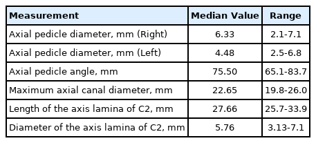
Morphometric measurements of C2
DISCUSSION
Posterior C1-2 screw instrumentation for immediate rigid atlantoaxial fixation was first described by Goel and Laheri in 1994 [18]. This technique was subsequently popularized by Harms and Melcher in 2001 after which C2 pedicle cannulation was commonly performed [19].
In our series, C1 screws were inserted through the PA entry point. Baorong et al. concluded that C1 fixation via the PA entry point is less invasive, simpler, has fewer complications and provides better fixation results [20]. However, the PA entry point presents greater risk of VA injury and C1 arch fracture [20]. Yi el al. found that PA entry point is an independent risk factor of screw malposition and total C1 screw complications [21]. Furthermore, PA screw placement is not always possible due to the anatomic variability of the C1 arch. The application of C1 screw fixation using the PA entry point is generally limited to a C1 arch height of 4 mm [22].
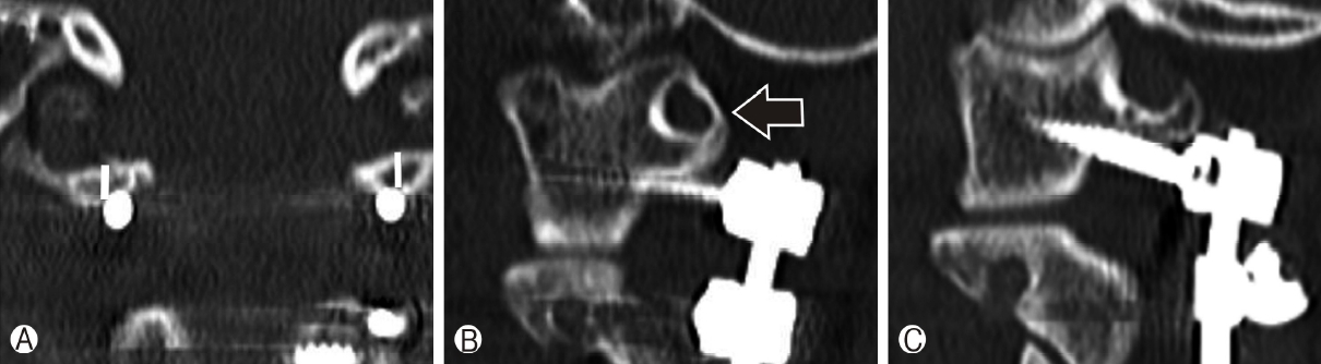
In our series, 3 medial breaches occurred. The causes of these malpositions were; the distance from the two malpositioned screw entry point to the midpoint of the C1 posterior tubercle was shorter than non-breach screws (22.38 mm vs. 15.94 mm) and the medial screw trajectory angle was smaller than the medial safety angle in the other (77.1° vs. 69.3°). (Fig. 4) These findings emphasize that the operator should carefully finding entry-point through surgical anatomy, and that the screw be inserted accurately. According to our anatomical measurements, the safe entry point distance from C1 posterior tubercle and screw trajectory are 22.38mm and 86.17°, and that if the height of the C1 arch is <4-mm or ponticulus posticus, the screw should be inserted using the C1 notching technique (Fig. 5). The entry point of notching technique is between the entry point of the C1 lateral mass screw and that of the C1 PA screw, which is at the junction between the C1 PA and lateral mass, and a little further from the paravertebral venous plexus and C2 nerve root. This higher-thannormal entry point reduces the risks of venous bleeding and C2 nerve injury [23].
C1 posterior arch screw insertion. (A) Trajectories and ideal placement of a PA screw on a postoperative cervical CT image. (B) Type IV medial breach, the distance from the screw entry point was shorter than the ideal distance (15.94 mm vs. 22.38 mm). (C) Type III medical breach, the screw trajectory angle was more acute than the ideal safety angle (69.3° vs. 77.1°).
C2 screws are inserted by pedicle, pars and translamina trajectory. While C2 pedicle placement can provide immediate axis fixation, great care must be taken not to injure the vertebral artery in the transverse foramen just lateral to the pedicle cortical wall [24]. The risk of vertebral artery injury after C2 pedicle screw placement has been reported to range from 4% to 6% [25], and thus, alternative C2 screws (pars and laminar) are recommended in the presence of HRVA to avoid neurovascular injury.
In the present study, the accuracies of C2 screw placement using a free-hand technique followed the order; pedicle>translaminar> pars screws. Of the 20 C2 screws placed, 15% exhibited a cortical breach, 85% were well placed, and 95% (19 screws) were acceptably placed. Although one translaminar screw was unacceptably placed (type IV medial breach), no symptomatic neurovascular complication occurred postoperatively (Fig.7A). To avoid this type of breach, length and diameter of axis lamina should be determined pre-operatively using CT images to estimate the diameter and length of the screw to be inserted. In this case of unacceptable placement, lamina diameter was only 3.13mm, and the median diameter for the other 9 patients was 6.12 mm. Thus, we recommend that a lamina diameter of >4mm is suitable for translaminar screw insertion. In addition, we recommend that a small hole be burred in the opposite lamina to check whether the screw has been inserted into the intra-lamina precisely(Fig. 7B).
Some previous studies support our results. Yeom et al. placed 46 C2 screws (39 pedicles and 7 laminar) using an anatomical free-hand method and reported 8 pedicle screws (21%) breached the vertebral artery foramen but did not cause arterial injury [26]. Sciubba et al. studied 100 C2 pedicle/pars screws in 55 consecutive patients and found 15 breaches (15%) but no symptomatic neurovascular injury [27]. Park et al. placed 117 alternative C2 screws and noted a cortical breach rate of 26.5%, 73.5% were well placed, and 98.3%(115 screws) were acceptably placed, but similarly, no symptomatic neurovascular complication occurred postoperatively [17]. These studies show C2 screw placement using the free-hand technique can be performed safely and effectively, and show mild cortical breaches do not result in clinical symptoms.
To ensure screw accuracy, preoperative imaging evaluations, and extensive intraoperative exposure of the medial, lateral, and superior aspects of C2 are important. In addition, the study shows attention to tactile feedback during free-hand screw insertion prevents high-grade cortical breaches.
The present study has several limitations that warrant consideration. Major limitations concern its retrospective, single-center, non-blinded design, and small sample size. Notably, we aimed to assess the safety of this instrumentation technique and did not investigate long-term or functional outcomes.
CONCLUSIONSummarizing, screw insertion for instrumentation of C1-2 vertebrae using the free-hand technique without intraoperative fluoroscopy or navigation was found to be safe and effective. Preoperative anatomic assessments for surgical planning and intraoperative tactile feedback ensured accurate screw placement. Finally, the study demonstrates that preoperative measurements of C2 morphometry are essential for choosing appropriate alternative C2 screws and preventing neurovascular complications.